Coordination Drawings in the BIM Workflow
On a modern HVAC project, most conflicts never reach the job site. They get solved earlier in a shared BIM model, then captured in a set of coordination drawings that installers can trust.
For YAOAN VENTILATION, coordination drawings translate a 3D clash-free model into clear layouts that show ducts, equipment, and access zones exactly as they should be built.
What an HVAC Coordination Drawing Actually Shows
A true coordination drawing does more than repeat design intent. It reflects field reality and agreements between trades. Typical HVAC content includes:
- Duct routes with final sizes, elevations, and offsets
- Locations for fans, air handling units, and major terminals
- Fire, smoke, and volume control dampers with access positions
- Clearances for maintenance, access doors, and future replacement
- Hanger and support zones that do not clash with other trades
These drawings sit on top of architectural, structural, electrical, and plumbing information so installers can see how everything fits together in one coordinated view.
Difference from standard design or shop drawings
Design drawings explain what the system should achieve. Shop drawings show how one trade plans to build its own scope. Coordination drawings pull all trades together and lock in a shared, constructible layout that everyone has reviewed.
BIM-based Coordination: From Model to Drawing
On BIM projects, coordination starts inside a combined 3D model. Each discipline maintains its own model, then the team merges them to find and fix conflicts.
A typical process for HVAC looks like this:
- YAOAN VENTILATION develops a detailed duct and equipment model from design documents.
- The BIM coordinator combines HVAC, structural, and other MEP models.
- Clash detection tools highlight intersections and clearance issues.
- The team agrees on changes at coordination meetings.
- The HVAC model updates to reflect the final, approved routes and levels.
Coordination drawings then come directly from this clash-resolved model, which keeps them consistent with the latest design agreements.
Typical BIM outputs for HVAC
Depending on project requirements, coordination drawings may include:
- Plan views by level with coordinated duct layouts
- Section cuts at tight areas such as corridors and shafts
- 3D views around major equipment rooms
- Riser diagrams that show vertical relationships between floors
These views help installers visualize not only where to place ducts and fans, but also how those elements relate to beams, ceilings, and other services.
Managing Conflicts with Other Trades
Conflicts rarely disappear on their own. A good coordination process shows how the project team resolves them in a structured way.
Common HVAC-related clashes
HVAC systems often clash with:
- Structural beams and brace frames
- Large cable trays or electrical busways
- Plumbing stacks and fire protection mains
- Architectural features such as low soffits or feature ceilings
Each clash forces a decision: move the duct, resize or reroute another service, adjust elevation, or change equipment selection.
Rules of thumb for resolution
To keep decisions fair and efficient, teams often follow simple priorities:
- Maintain structural integrity and fire separations first.
- Protect major equipment locations and critical slopes.
- Shift smaller or more flexible services when space runs tight.
- Preserve access to valves, dampers, and inspection doors.
Coordination drawings document the final outcome, so crews do not need to renegotiate those decisions in the field.
How Coordination Drawings Support Construction and Safety
Coordination drawings give installers and inspectors a common reference. That support extends beyond basic routing.
Benefits for installation teams
Field crews use coordination drawings to:
- Prefabricate duct sections with confidence in their dimensions
- Plan lifts and deliveries around confirmed equipment positions
- Install hangers and sleeves in the correct locations on the first attempt
- Avoid rework caused by hidden clashes with other trades
Better coordination means fewer changes on site and a safer, cleaner work environment.
Benefits for FIRE SAFETY and maintenance
From a safety perspective, coordination drawings help ensure:
- Fire and smoke dampers sit in correct rated barriers
- Access doors remain visible and reachable after ceilings go in
- Critical clearances for egress and smoke-control equipment stay open
These documents support inspectors and facility teams long after construction ends.
FAQ
What is the difference between shop drawing and coordination drawing?
A shop drawing shows how a single trade plans to fabricate and install its scope, such as ductwork or piping. A coordination drawing combines information from multiple trades and resolves clashes so all systems fit together. Shop drawings feed into coordination; coordination drawings lock in the shared, buildable layout.
What does coordination mean in construction?
In construction, coordination means aligning the work of different trades so that systems fit within the building without conflicts. It covers routing, sequencing, access, and clearances. Effective coordination reduces rework, improves safety, and helps the project meet schedule and quality targets.
What is MEP coordination drawing?
An MEP coordination drawing shows mechanical, electrical, and plumbing systems together in one view. It captures the agreed routing, elevations, and clearances after clashes have been solved in BIM or detailing sessions. Installers use these drawings as the primary reference when positioning services.
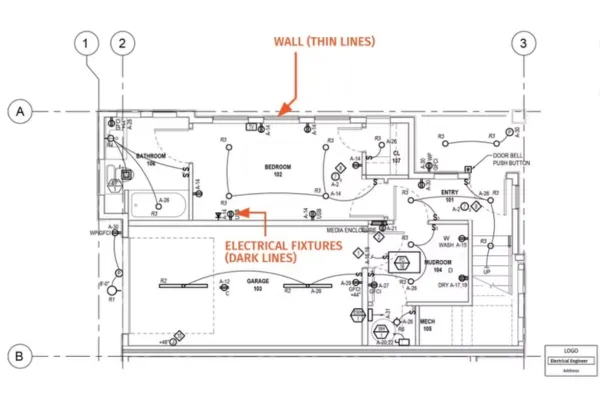
What is wall coordination drawing?
A wall coordination drawing focuses on items that pass through or sit within walls, such as ducts, pipes, electrical raceways, and access panels. It helps designers and contractors align openings, sleeves, firestopping, and finishes, so services fit correctly and the wall’s fire and acoustic performance remains intact.
What is a coordination drawing?
A coordination drawing is a construction document that shows how multiple building systems fit together in a specific area. It results from a clash-resolution process and provides final, dimensioned layouts that installers can follow. In HVAC work, it confirms duct routes, equipment positions, and relationships to other trades.
What are the three types of construction drawings?
Many teams group construction drawings into three broad types: design drawings that define intent, shop drawings that show trade-specific fabrication and installation, and record or as-built drawings that document what was actually built. Coordination drawings typically sit between design and final shop information.
What are the three classes of drawings?
In some contexts, drawings are classified as concept-level, detailed design, and construction or fabrication class. Concept drawings explore options; detailed design drawings set dimensions and performance; construction-class drawings provide the information crews need to install and assemble systems on site.
What does IFC drawings stand for?
IFC drawings usually stand for “Issued for Construction” drawings. These are the versions approved for use on site after design review and coordination. Contractors rely on IFC drawings, together with coordination and shop drawings, to guide installation work and meet project requirements.
About YAOAN VENTILATION
YAOAN VENTILATION delivers optimized air and airflow management solutions backed by nearly three decades of engineering experience. Since 1996, we have focused on industrial-grade ventilation and fire protection systems for commercial buildings, infrastructure, and specialized environments. Our teams develop detailed BIM models and coordination drawings for fans, duct systems, dampers, and smoke-control components, helping projects avoid clashes and protect FIRE SAFETY performance. By combining precise coordination with robust equipment, YAOAN VENTILATION supports smoother installation, clearer maintenance access, and long-term confidence in every system.